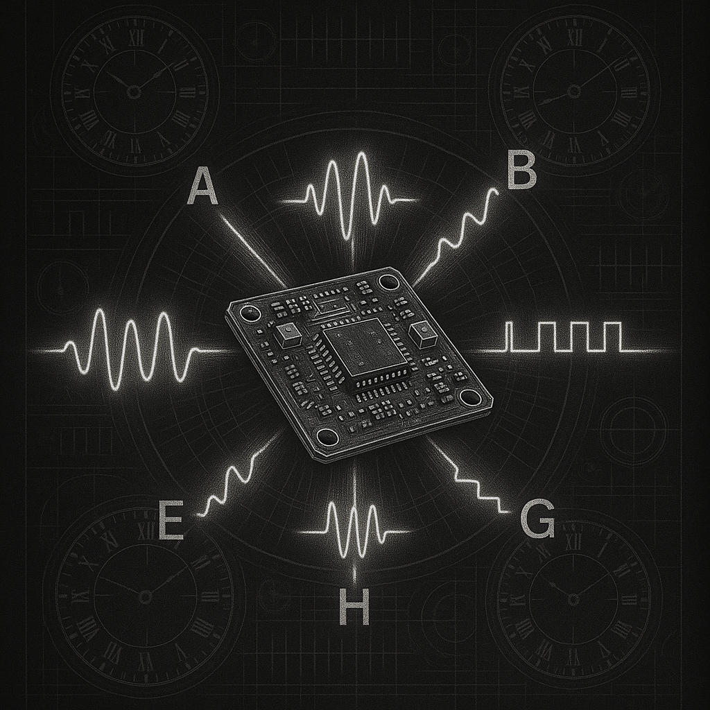

IRIG Master Core
IRIG Master Core Overview
The IRIG core has been designed to allow easy adaptation for any application. The standard formats for transferring timing information are given with the appropriate time frame for each format and provide valid timing information for each IRIG version.
The design is fully synchronous to a single system clock input and has an asynchronous reset with configurable polarity.
The core accepts various timing and control inputs as shown in table 4. For every IRIG format the Master will stream IRIG data according to the standard and the time scale for the particular standard.
Feature Summary
- IRIG Standard 200-16 Compliant
- Supports time frames ranging from 10 milliseconds up to 1 minute.
- Support for IRIG- A, B, E, G, and H standards
- Configurable to accept a wide range of input clock frequencies.
Agilex 5 Utilization Report
| IRIG Format | ALMs | FFs | LUTs |
|---|---|---|---|
| A | 182 | 234 | 215 |
| B | 176 | 226 | 219 |
| E | 177 | 226 | 223 |
| G | 175 | 226 | 213 |
| H | 108 | 140 | 160 |
Virtex 7 Utilization Report
| IRIG Format | FFs | LUTs |
|---|---|---|
| A | 195 | 102 |
| B | 194 | 107 |
| E | 201 | 111 |
| G | 181 | 85 |
| H | 181 | 85 |
Figure 1 – IRIG Master Interface Top Level I/O
IRIG standards timing frames
| G | A | B | E | H | |
|---|---|---|---|---|---|
| Time frame | 10 ms | 100 ms | 1 sec | 10 sec | 1 min |
| Bits per frame | 100 | 100 | 100 | 100 | 60 |
| Bit time | .1 ms | 1 ms | 10 ms | 100 ms | 1 sec |
IRIG min and max clock frequencies
| Clock Freq. | G | A | B | E | H |
|---|---|---|---|---|---|
| Minimum | 10MHz | 1MHz | 100KHz | 10KHz | 1KHz |
| Maximum | 200MHz+ | 200MHz+ | 200MHz+ | 200MHz+ | 200MHz+ |
IRIG standards inputs
| Input Signals | G | A | B | E | H |
|---|---|---|---|---|---|
| time valid | x | x | x | x | x |
| hundredths | x | ||||
| tenths | x | x | |||
| seconds | x | x | x | x | |
| minutes | x | x | x | x | x |
| hours | x | x | x | x | x |
| date | x | x | x | x | |
| month | x | x | x | x | |
| year | x | x | x | x | |
| control | x | x | x | x | x |
| time sec | x | x | x | ||
| days | x | x | x | x | x |